Four legs balancing and exercises

Over the spring, from the beginning of March until the end of May, I focused on balancing Continuity. I tried many different approaches to gain experience and acquire critical thinking in selecting the best one.
- The first one is probably the most complex and common in robot control systems: Proportional Integral Derivative control, or PID. The balancing algorithm was working fine, as can be seen from this video. The PID control is not fine-tuned, but even without doing it, I immediately noticed something I didn't like: motors were weakening approaching the desired position, and losing torque. This behaviour is not normal and it might be caused by an incorrect setup of the power distribution system. Additionally, the servo motors were sometimes rotating to undesired positions, I guess due to overlapping signals (?), causing damage to the mechanical structure of the legs.
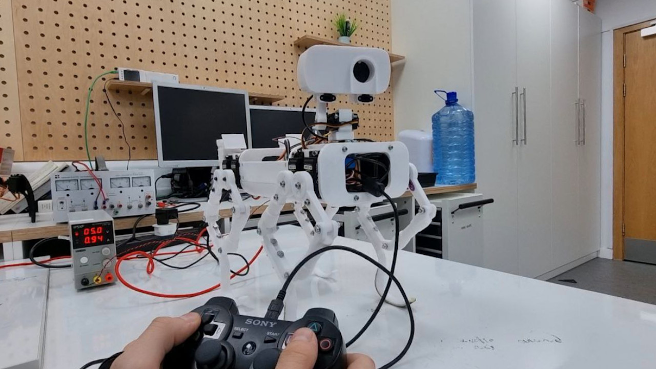
Joypad integration

During the last few weeks of testing, I integrated a joypad into Continuity's control methods. This was done to simplify testing on the robot, improving precision and making things a bit more fun when it comes to having a quick demo available to show to people (this happened multiple times, in the past few weeks). I chose to connect a PS3 joypad using the comprehensive features offered by the "Gamepad" GitHub repository. This repository not only simplifies the process but also provides users with multiple joypad configurations, catering to diverse testing needs. In an initial trial, I focused on controlling the Remote Sensing Mast (RSM), a pivotal element of the rover that comes with two degrees of freedom: azimuth rotation and elevation. The RSM serves critical functions such as capturing photos, and panoramic images and facilitating autonomous navigation by aligning with the direction of movement. Subsequent tests focused on legs extension and other general movements, all executed seamlessly through joypad control. While these tests may appear useless given Continuity's ultimate autonomous functionality, being able to control the robot in a user-friendly way is actually extremely important for something that I'm working on aside. I'm trying to develop a simulation framework using Blender, the same open-source software I used for 3D modelling Continuity. Blender is capable of running rigid body simulations and being able to interface them with a Python script might allow me to use it as a real-time simulation tool. More updates will follow on this topic.
Rapid Unscheduled Disassembly

We are not talking about rockets, but apparently, I had to face a Rapid Unscheduled Disassembly of the Mast Tower's head. It doesn’t take a degree in aerospace engineering to know that, ideally, rockets aren’t supposed to blow up. Similarly, a robot is not supposed to break apart during a test. However, this is exactly what happened. During the test, a coding error made one leg go rogue, turning the robot into a bit of a daredevil and resulting in a not-so-graceful tumble from the table. Luckily, the legs and other moving parts survived the crash, but poor Continuity's neck got the worst of it. The elevation mechanism to control the pitch angle of the Imager (the head of the Remote Sensing Mast), is a simple 3D-printed extension of an aluminium servo motor horn. This helps reduce the mechanical complexity, but also makes it much more fragile when the robot has to survive a fall.
Lesson learned: While we love keeping things light and simple, we've got to find that sweet spot between lightweight design and toughness. I am patching up Continuity, adding some extra code safety features, and making sure the robot is ready to handle whatever comes its way. Here's to smoother tests in the future!
Imager camera and TOF sensor
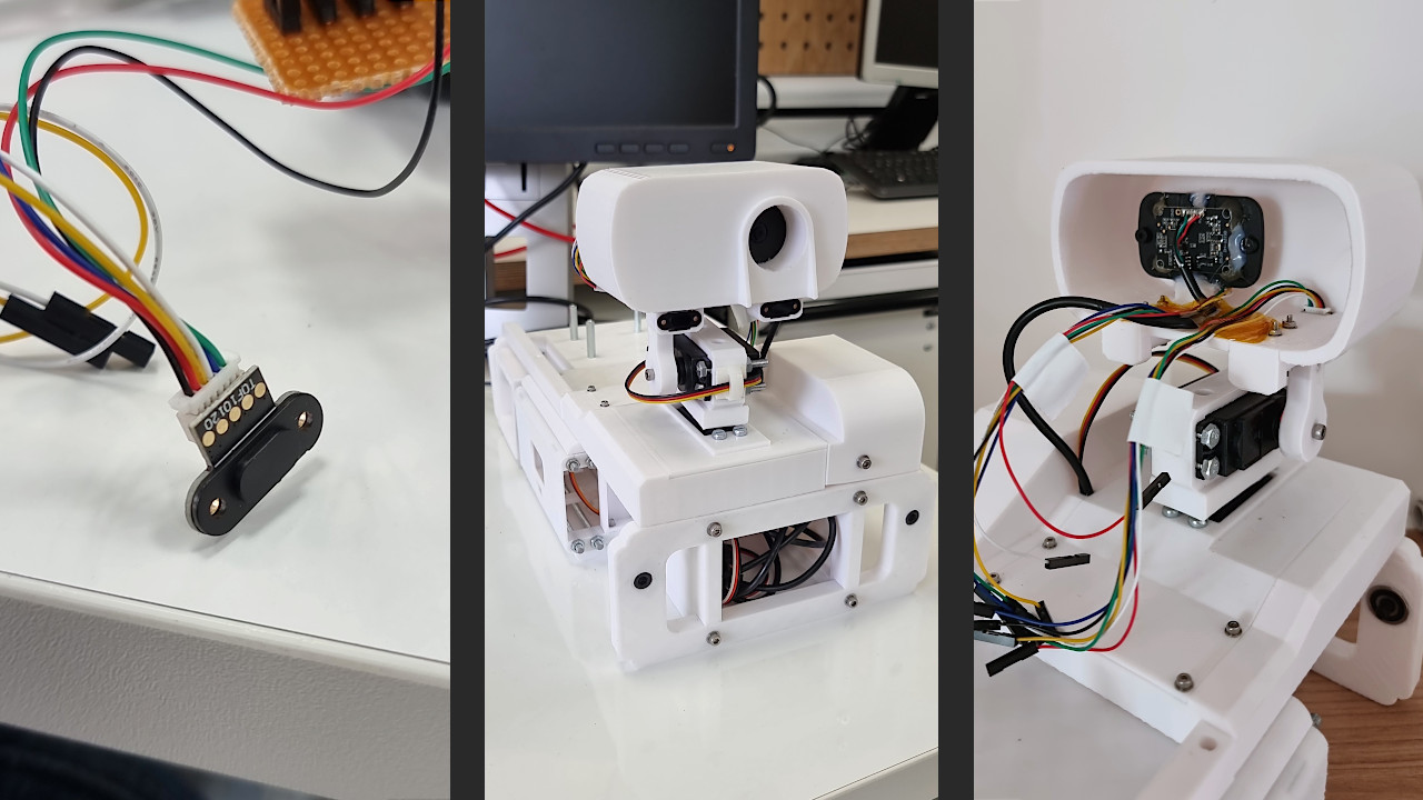
The Imager, that is to say, the top part (or head) of the Mast Tower is the key that justifies the existence of the tower itself: elevating the main rover camera, giving it rotation freedom in all directions. At its current state, Continuity's Imager is equipped with a 1080p camera and a couple of 10120 TOF sensors. A TOF (Time of Flight) is a sensor commonly used on drones due to its extremely low weight. It allows the rover to estimate in real-time the distance between the sensor and an object counting the time light takes to go back and forth from it. Since its precision is not always ensured, I installed a couple of them for redundancy and to get an average of their measurements, obtaining a more reliable value. There is still plenty of space inside the Imager, but this is fine because this will not be its final look, and many parts still need to be improved: for instance, the height of the Mast Tower, which risks being too high compared to the rover centre of mass.
