Melting and Fitting.

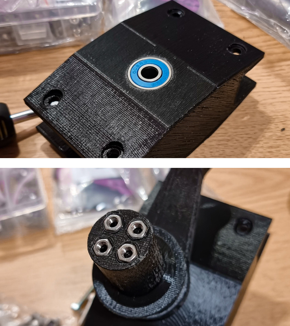
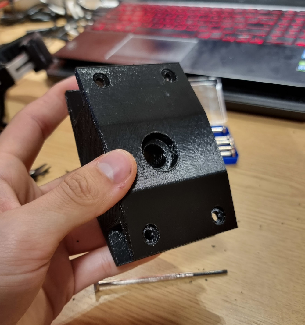
Using a budget provided by Napier University to all students of Engineering, some components were purchased to proceed with the assembly of the rover. These parts are mainly bearings, nuts and bolts of different sizes, as well as threaded rods and other minor items. All components have been carefully selected to ensure rock-steady stability for the rover. In order to guarantee a precise fitting, the 3D printed parts already have holes with the actual diameter of the bolts: before starting the printing process, the Horizontal Expansion has been set to -0.1mm, to avoid any possible fitting error due to an over-expansion of the melted plastic. However, a trick was used to improve the fitting even more: all bearings, nuts and bolts purchased were <1mm larger than they should have been: in order to fit them in the correct holes, all metal components were pre-heated and pushed in position using a tin soldering iron (tin soldering iron temperature: 200°C). This technique was used also to fill small cracks and errors due to the 3D printing process: the hot soldering iron was heat-up and used together with a PLA filament; the result is what can be called "plastic soldering". This is clearly visible in the two pictures shown below.

  • [Hours of work: 4h]
  • [People involved: Giorgio]

enter image description here

Scarecraw.

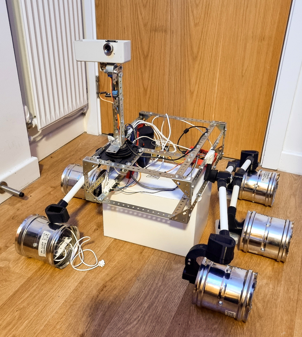
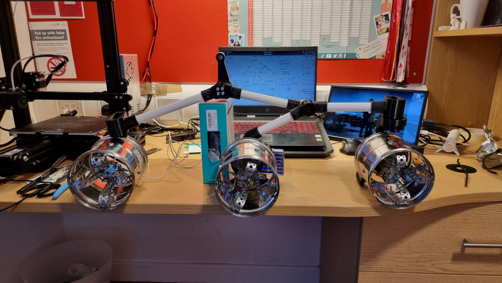
With more the half of the components of the Rocker Bogie suspension system ready, it was attempted an assembly of the parts, in order to obtain (roughly) the shape of the rover. Even if the structure looks almost entirely assembled, all bearings, nuts and bolts are missing, as well as some of the brackets of the steering wheels (LHS of the picture). Despite that, this is the first time the shape of Mimas is clearly visible!

  • [Hours of work: 1h]
  • [People involved: Giorgio]

enter image description here

MOBM and DU.

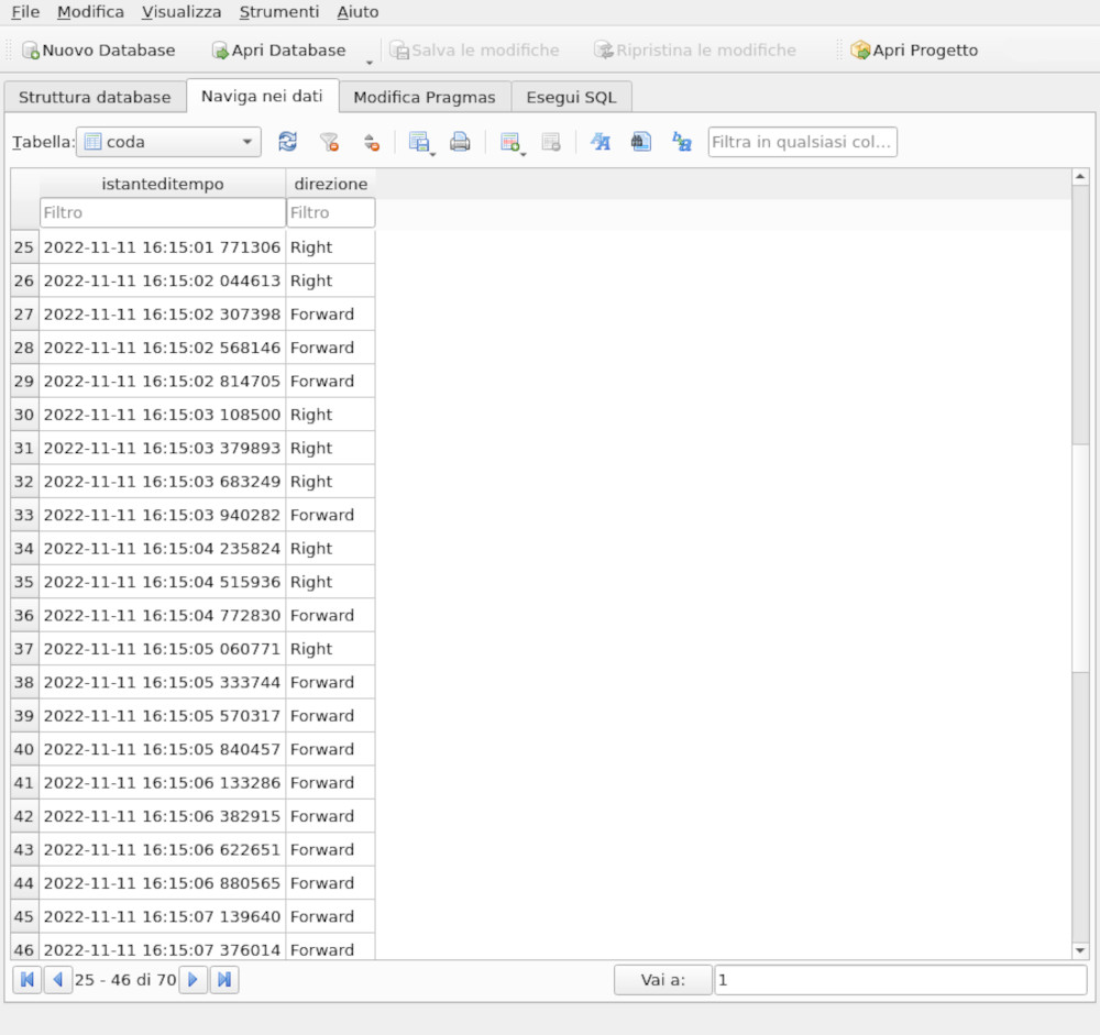
Mimas autonomous navigation will be managed by several modular units, each of which has a precise role in taking photos, deciding the best direction where to go, and actually activating the motors. All these systems are controlled by the Mobility Manager (MOBM), which takes all input data, ignores the values that are not in an acceptable range, and does value conversions if needed. The MOBM communicates directly with the Drive Unit (DU), providing it with data stored in an SQLite embedded Database. The data producer (path planning algorithm and/or obstacle-avoidance algorithm) releases a high amount of data in a very short time, while the data consumer (DU) is much slower since the rover drives very slowly. SQLite is a great option for this type of system since it is reliable and portable: the algorithm can be moved from one machine to another and it is multiplatform (it runs on common computers like Linux, Windows or macOS machines, or Rasberry Pi).

  • [Hours of work: 3h]
  • [People involved: Giorgio]

enter image description here

Edinburgh SpaceUp Unconference.

SpaceUp Scotland has been a great occasion to meet people and experts interested in Space, rocketry and robotics. I (Giorgio's speaking) had to opportunity to present the "Mimas" project to a Space Scotland representative, ESA Ambassador, and other Professionals, asking for advice and listening to their opinion about the project. In addition, I got some useful advice for my future after graduation. I attended from 10 am to 7 pm. A group photo will be published as soon as it will be realised by SpaceUp.

  • [Hours of attendance: 9h]
  • [People involved: Giorgio]

enter image description here

A new look.

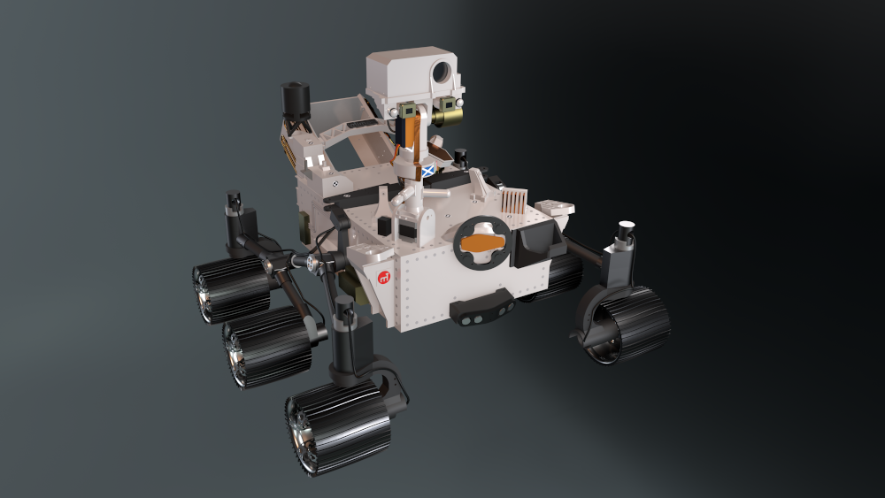
In the past five months, the 3D model of Mimas had several changes: the design was updated continuously to improve the similarity with Perseverance and Curiosity. However, some parts are constrained due to the shapes of the electronic components and the chosen motors. The rendering shown below is the most complete ever made for now: the shape and material are as close as possible to the real look Mimas will have. Surely, additional updates will be made to this model to increase its realistic look and amount of detail.

  • [Hours of work: 6h]
  • [People involved: Giorgio]

enter image description here

Just enough cameras!

Taking advantage of a good discount, four webcams were purchased to reach the total final amount of cameras needed on board. They are all 720p HD cameras with USB connectors, ideal for computer vision tasks since the video stream is light enough for a Rasberry Pi. Full HD cameras (1080p) are also great, but one of the objectives of this project is to make the system as light as possible. Anyway, the four webcams will be added to the already existing three cameras to get a total of seven onboard cameras that will be used for the following purposes: 1x MasterCam (on the Mast), 2x NavCam (Navigation Cameras - on the Mast), 1x HazCam (Hazard Camera - rear of the rover), 2x SurCam (Surrounding Camera - LHS and RHS of the rover).

  • [Hours of work: -]
  • [People involved: Giorgio]

enter image description here

The "Green Lines Algorithm"

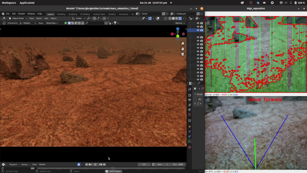
Mimas Rover will have an autonomous navigation capability and to achieve it, multiple systems will be used, one of which is the "Green Lines Algorithm" (GLA). This algorithm is still a work in progress, since June 2022. This post will not go in-depth with this algorithm since it still needs several improvements. In order to do some tests (the rover structure is not ready yet, hence a real driving test is impossible at the moment) a simulation of the Mars surface was made, modelling the terrain in Blender. Then, a webcam was placed in from of the laptop screen and the algorithm was run to test its efficiency. Despite the results are still not great and the GLA requires several improvements, the main principle of the algorithm showed to work correctly: rocks and possible hazards are detected!

  • [Hours of attendance: >20h]
  • [People involved: Giorgio]

enter image description here

The rocker joint base.

The rocker joint base is one of the parts subjected to continuous stresses while the rover is driving. There is one rocker joint base located at each side of the RB suspension system. These couple of components handle the entire rover's weight, so they must be very stiff and ready to resist stresses. Printing the first piece required 21 hours and 25 minutes, so will be for the second one.

  • [Hours of work: 4h]
  • [People involved: Giorgio]

enter image description here

Stereo vision.

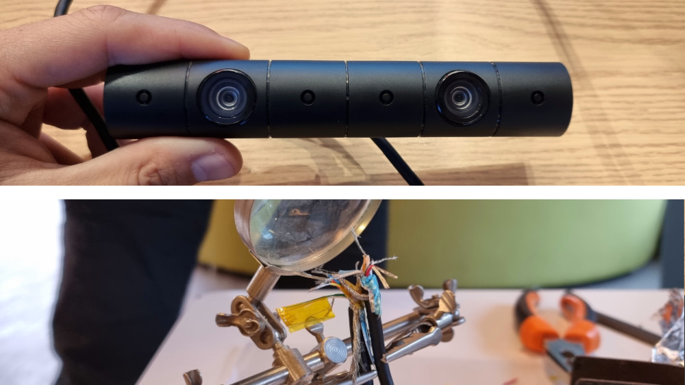
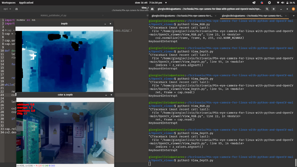
Stereo vision is how humans perceive depth. The word "stereo" means “two.” Humans look at the same scene from two different viewpoints to get a sense of depth. So, in order to simulate it, two identical cameras are required: a gaming console stereo camera was bought for this purpose. However, the company that produced the camera made a custom USB 3 cable connector, to let it be usable only on their consoles. To overcome this problem, a common USB 3 cable was cut and tin-soldered to the camera cable, essentially stitching them together. This operation required a series of delicate steps and, in the end, all cables were shielded to avoid electromagnetic interferences while operating. Another challenge was to implement custom open-source firmware to communicate directly with the camera hardware. The final result works quite well and a few depth perception tests were carried out.

  • [Hours of work: 4h]
  • [People involved: Giorgio, Akshit]

enter image description here

enter image description here

Halfway there!

After several days of printing, the first half of the Rocker-Bogie suspension system is ready! The PVC tubes used to connect all printed parts together are not very likely to be used in the final design, since they may be too flexible. At the moment, the plan is to substitute them with aluminium tubes to ensure a higher stiffness as well as a lightweight structure. Nevertheless, the picture below gives an idea of the final shape of one-half of the suspensions, for the first time. A closer look will show that the "C" shaped bracket of the wheel on the left-hand side is missing, so the servo motor mount is simply leaning on the wheel. If everything goes as planned, this assembly should be ready for testing, with bearings, bolts and nuts in the correct place, in three weeks.

  • [Hours of work: 1h]
  • [People involved: Giorgio]

enter image description here